| MAGNABEND TROUBLE SHOOTING GUIDE |
Trouble Shooting Guide
The following applies to Magnabend machines made by Magnetic Engineering Pty Ltd up to about the year 2004.Since the expiry of patents (owned by Magnetic Engineering) other manufacturers are now making Magnabend machines which may not be exactly the same. Therefore the information below may not be applicable to your machine or it may need to be adapted.
The easiest way to fix electrical problems is to order a replacement electrical module from the manufacturer. This is supplied on an exchange basis and therefore is quite reasonably priced.
Before sending for an exchange module you may like to check the following:
CASE 1 - The machine does not operate at all:
(a) Check that power is available at the machine by observing the pilot light in the ON/OFF switch.
(b) If power is available but the machine is still dead but feels very hot then the thermal cut-out may have tripped. In this case wait until the machine cools down (about ½ an hour) and then try it again.
(c) The two-handed starting interlock requires that the START button is pressed before the handle is pulled. If the handle is pulled first then the machine will not operate. Also it may happen that the bending beam moves (or is bumped) sufficiently to operate the "angle microswitch" before the START button is pressed. If this happens make sure the handle is pushed fully back first. If this is a persistent problem then it indicates that the microswitch actuator needs adjustment (see below).
(d) Another possibility is that the START button may be faulty. If you have a Model 1250E or larger then see if the machine can be started with one of the alternative START buttons or the footswitch.
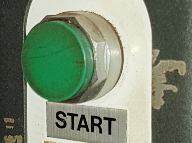 START button. |
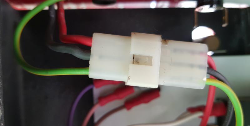 Nylon coil connector. |
(e) Also check the nylon connector which connects the electrical module with the magnet coil.
(f)
If clamping does not operate but the clampbar
snaps
down on release
of the START button then this indicates that the 15 microfarad (10 µF
on the 650E) capacitor is faulty and will need to be replaced.
CASE 2: The machine blows external fuses or trips circuit breakers:
The most likely cause of this behaviour is a blown
bridge-rectifier.
A blown rectifier will usually have at least one of its 4
internal diodes shorted.
This can be checked with a multimeter. With the meter on its
lowest resistance range check between each pair of terminals.
One polarity of the multimeter test leads should show
infinity ohms and the reversed polarity should show a low reading, but
not zero. If any resistance reading is
zero then the
rectifier is blown and must be replaced.
Make sure that the machine is unplugged from the power outlet before attempting internal repairs.
| A
suitable replacement rectifier : RS Components part number: 227-8794 Max current: 35 amps continuous, Max reverse voltage: 1000 Volts, Terminals: 1/4" quick-connect or 'Faston' Approx price: $12.00 |
 |
Rectifier circuit:
 |
CASE 3: The magnet coil is shorted to the magnet body.
To check for this unplug the magnet coil connector and measure the resistance, from either the red or black lead, to the metal of the magnet body. Set the multimeter to its highest resisance range. This should show infinity ohms when connected as instructed above..
Idealy this measurement should be made with a "Megger meter". This kind of meter checks the resistance with a high voltage (typically 1,000 volts) applied. This will find more subtle insulation breakdown problems than can be found with an ordinary multimeter.
Insulation breakdown between the coil and the magnet body is a serious problem and normally would require the coil to be removed from the magnet body for repair or replacement with a new coil.
CASE 4: Light clamping operates but full clamping does not:
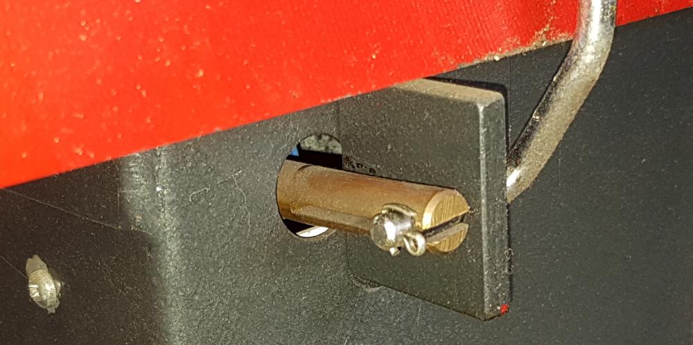
Check that the "Angle Microswitch" is being actuated correctly.
[This switch is operated by a square (or round) brass piece which is attached to the angle indicating mechanism. When the handle is pulled the bending beam rotates which imparts a rotation to the brass actuator. The actuator in turn operates a microswitch inside the electrical assembly.]
 Microswitch
actuator on the Model 1000E
(Other models use the same principle) |
 Actuator as
seen from inside the electrical
assembly. |
Pull the handle out and in. You should be able to hear the microswitch clicking ON and OFF (provided there is not too much background noise).
If the switch does not
click ON and OFF
then swing the bending beam right up so that the brass actuator can be
observed. Rotate the bending beam up and down. The
actuator should rotate in response to the bending beam (until it
clutches at its stops). If it does not then it may need more
clutching force:
- On the 650E and 1000E the clutching force can be increased by removing the brass actuator and squeesing the slit closed (eg with a vice) before reinstalling it.
- On the 1250E lack of clutching force usually relates to the two M8 cap-head screws at either end of the actuator shaft not being tight.
If the actuator rotates and clutches
OK but still does not click the microswitch then it may need
adjusting. To do this first unplug the machine from the power
outlet and then remove the electrical access panel.
a) On the Model 1250E the turn-on point can be adjusted by turning a
screw which passes through the actuator. The screw should be
adjusted such that the switch clicks when the bottom edge of the
bending beam has moved about 4 mm. (On the 650E and 1000E the
same adjustment is achieved by bending the arm of the microswitch.)
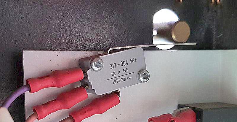
b) If the microswitch does not click ON and OFF even
though the
actuator is working properly then the switch itself may be fused inside
and will need to be replaced.
Make sure that the machine
is unplugged from the power outlet before attempting internal repairs.
| A
suitable
replacement V3 switch: RS part number: 472-8235 Current rating: 16 amps Voltage rating: 250 Volts AC Lever type: long Terminals: 1/4" quick-connect Approx price: $5.00 |
 |
V3 Circuit C= 'Common'
NC= 'Normally Closed' NO= 'Normally Open'  |
c) If your machine is fitted with an auxiliary switch then make sure it is switched to the "NORMAL" position. (Only light clamping will be available if the switch is in the "AUX CLAMP" position.)
CASE 5: Clamping is OK but Clampbars do not release when the machine switches OFF:
This indicates a failure of the reverse pulse
demagnetising
circuit. The most likely cause would be a blown 6.8 ohm power
resistor. Also check all diodes and also the possibility of
sticking contacts in the relay.
Make sure that the machine
is unplugged from the power outlet before attempting internal repairs.
 A
suitable
replacement resistor :
A
suitable
replacement resistor :Element14 part No. 145 7941
6.8 ohm, 10 watt power rating.
Typical cost $1.00
Case 6: The machine will not bend heavy gauge sheet:
a) Check that the job is within the specifications of the machine. In particular note that for 1.6 mm (16 gauge) bending the extension bar must be fitted to the bending beam and that the minimum lip width is 30 mm. This means that at least 30 mm of material must project out from the bending edge of the clampbar. (This applies to both aluminium and steel.)
Narrower lips are possible if the bend is not the full length of the machine.
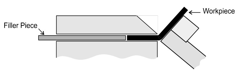
b) Also if the workpiece does not fill up the space under the clampbar then performance may be affected. For best results always fill up the space under the clampbar with a scrap piece of steel the same thickness as the workpiece. (For best magnetic clamping the filler piece should be steel even if the workpiece is not steel.)
This is also the best method to use if it is required to make a very narrow lip on the workpiece.
Contact Alan Magnabend Homepage Alan's Homepage